Another DIY HF Current Probe
Current probes are a valuable tool for EMC/EMI issues troubleshooting. Current probes are basically high frequency current transformers used to measure the common mode current (CM) through a conductor or cable. There are many commercial options available costing from hundreds up to thousands of dollars/pounds/etc. In this article, I will show you how to build your own HF current probe for a few bucks. Even such a simple and inexpensive tool can enabling you to get start troubleshooting EMC/EMI issues.
The RF current probe is a type of radio frequency current transformer. When the probe is clamped over the conductor or cable in which current is to be measured, the conductor forms the probe primary winding.
If you want to understand RF current transformers in more detail you can found good material here and here.
Figure 1 shows a Fischer F-52 probe. The commercial probes work really well, have specified bandwidth and power handling characteristics, built in shielding, robust case, etc. However with simple components we can build our own HF current probe device suitable for EMC/EMI troubleshooting.
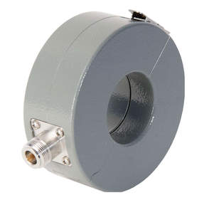
Figure 1 - Fischer F-52 Current Probe
My Probe
I have built my probe using the following materials:
- 1 x WÜRTH ELEKTRONIK 742 715 5, Snap Ferrite
- 1 x Panel-mount BNC connector
- 0.05 mm² wire (RS 359-908)
- Glue
- Electrical tape
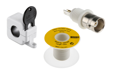
Figure 2 - DIY Current Probe Materials
I followed the article The HF Current Probe: Theory and Application from Kenneth Wyatt to make this DIY Current Probe. However, I have changed the number of turns in order to accommodate better to my chosen ferrite.
I started getting 6 turns of the white wire around one half of the ferrite core as shown in Figure 3.
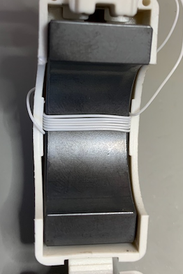
Figure 3 - Turns around ferrite core
Next step is fix the BNC connector with some super glue and solder the wires from the coil as shown in Figure 4.
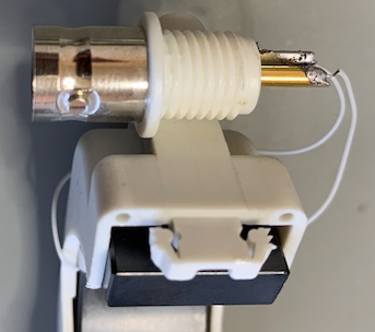
Figure 4 - BNC connector
Figure 5 shows the finished DIY Current Probe. Last thing was protected the wire coil with some white electrical tape and reinforce the BNC fixation with some hot glue
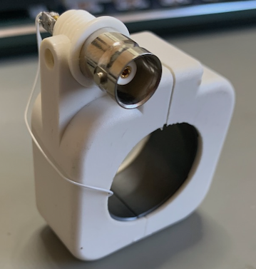
Figure 5 - DIY Current Probe
A-B Comparison
After built the probe, the next step is compare it with a commercial product. I have compared the DIY probe with the Fischer F-52 showed in Figure 1. To do that I have used a LM25574 Evaluation Board (Figure 6) as noise generator and measure the noise with both DIY and F-52 separately.
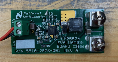
Figure 6 - LM25574 Evaluation Board
Figure 7 shows the test layout and how both F-52 and DIY probe were campled around the Evaluation Board DC power supply.
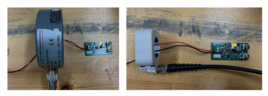
Figure 7 - DIY & F-52 Test Layout
Figure 8 shows the comparison result. As can be seen the DIY probe performance is very good for this frequency range (10kHz to 30MHz). Of course it does not replace a commercial product, but can be an excellent tool for troubleshooting, and give you an idea what’s going on with your system.
Figure 8 - DIY vs Commercial Probe
Probe Calibration
The calibration or characterisation of the DIY probe means found its Transfer Impedance curve, I’ve followed the same process described in the article “The HF Current Probe: Theory and Application” by Kenneth Wyatt. Another great paper is the “Do-It-Yourself current probe characterization for EMC troubleshooting”. Both documents can be found in the reference section.
I set the signal generator to an amplitude of \(224mV\) which in a \(50\Omega\) load will generate an output of \(0dBm\) or \(73dB\mu A\). Wyatt’s article [1] explains in detail all math behind that. The DIY probe was calibrate for the frequency range between 10kHz and 500MHz. Figure 9 shows the DIY probe Transfer Impedance for this frequency range.
Figure 9 - DIY Probe Transfer Impedance
Figure 10 shows the Transfer Impedance for the DIY probe versus F-52 probe.
Figure 10 - DIY vs F-52 Probe Transfer Impedance
Some variation can be noticed between 30MHz and 90MHz, which could maybe be caused by the test gear (need further investigation).
Summary
With a couple bucks or even with recycle parts you can create your own HF current probe. The DIY probe has some drawbacks if compared to commercial solutions. However, for troubleshooting and field applications, the DIY probe is good enough. Also, making your own current probe its a great way to really understand how it works and how it can be uses to identify EMC/EMI problems.
References
[1] https://interferencetechnology.com/the-hf-current-probe-theory-and-application/
[2] https://www.arbenelux.com/wp-content/uploads/2020/02/Current-Probe-Calibration-Application-Note.pdf
[3] https://interferencetechnology.com/calibration-of-toroidal-current-measurement-probes-at-high-frequency/
[4] http://g3ynh.info/zdocs/bridges/Xformers/part_1.html
[5] http://emcesd.com/pdf/iprobe98.pdf
[6] https://ieeexplore.ieee.org/document/7050567


