Simulate FPGA VHDL using QUCS for free
Qucs is a free open source electronic multiplataform circuit simulator that can be used to simulate analog and digital electronic circuits. Qucs is fully integrated to the FreeHDL that’s a free VHDL compiler/simulator.
1. Installation
The first step is download and install Qucs. Click here to download. Next step is install the FreeHDL application. How to perform this step depends of your operational system.
Windows
For windows users all packets need are available on that link.
Linux
For linux users for debian based distribution, use apt-get to install the package.
1
$ sudo apt-get install freehdl
MacOs
For MacOs users use brew application installer to get install the package.
1
2
3
4
# brew tap guitorri/tap
# brew unlink libtool && brew install libtool # was failing to update under gcc-5~
# HOMEBREW_CC=gcc-5 HOMEBREW_CXX=g++-5 brew install freehdl++
# brew link libtool
May will be necessary to install the gcc5 compiler as well.
1
# brew install gcc@5
2. Simulate you first VHDL code
The circuit that we’ll simulate is a simple AND digital gate.
-
Start QUCS
-
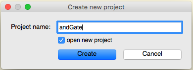
As soon the main screen showed up will create a new empty project. To create new project click the New Project menu item on the Project main menu.Give the name andGate for you new project and click on Create button.
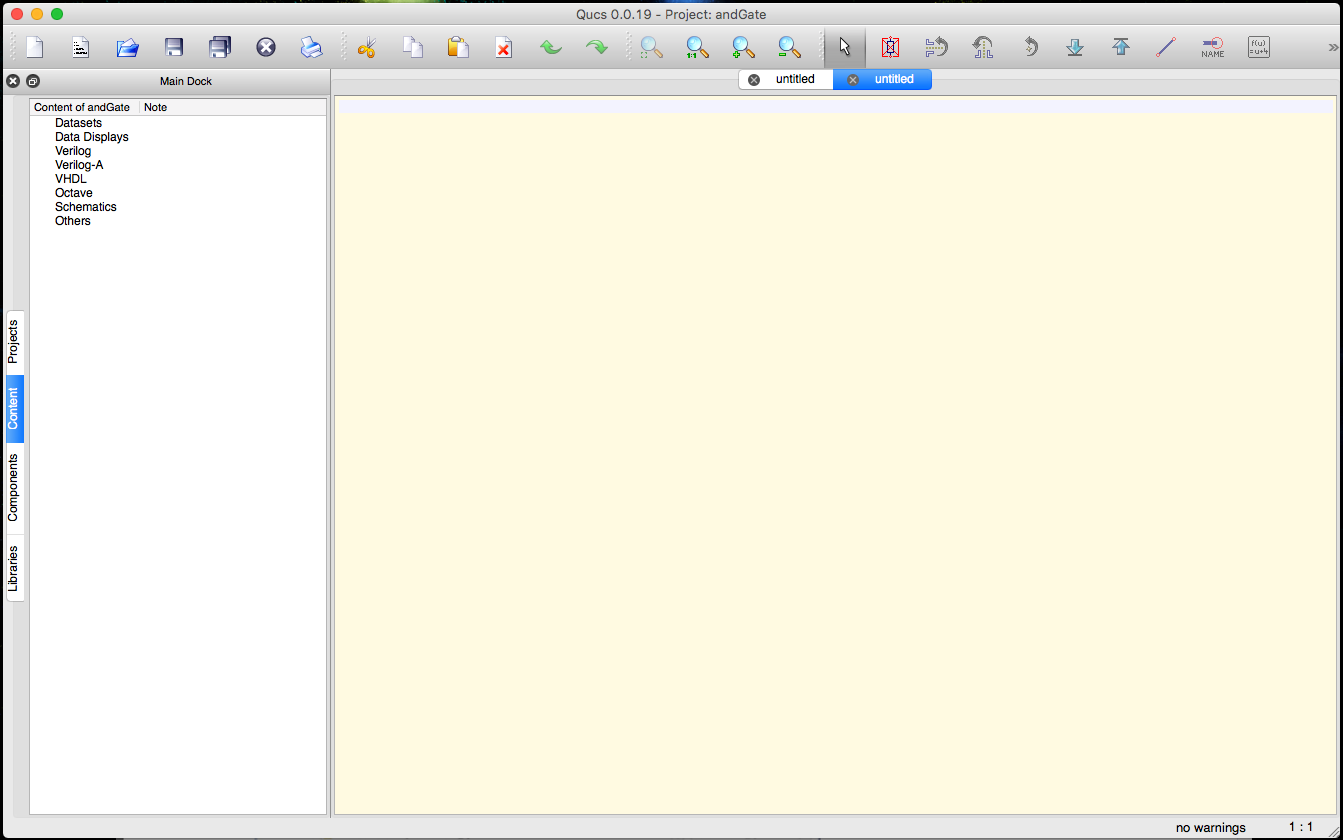
- Select New Text on the File menu. A empty text file screen will be opened.
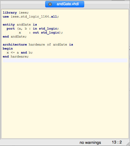
- Now you can enter your VHDL code for the AND gate. The code source is below.
1
2
3
4
5
6
7
8
9
10
11
12
13
14
15
16
17
-------
--- Project: AND Gate VHDL simualation
---
--- 2018 by Vanderson Pimenta <vandersonpc@gmail.com>
-------
library ieee;
use ieee.std_logic_1164.all;

entity andGate is
  port (a, b : in std_logic;
		x    : out std_logic);
end andGate;

architecture hardware of andGate is
begin
  x <= a and b;
end hardware;
- Click the Save button or select the menu File > Save as.. use as file name the save name of the HDL entity. i.e. andGate.vhdl. After saved the editor will enable the syntax color highlighting which is very useful.
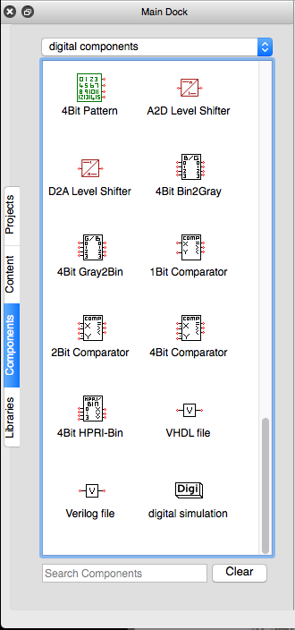
- Now select or create an untitled schematic. Select on left pane Components and on the dropdown menu select digital components. On the digital components list select the VHDL file component.
- Double click on the new VHDL file component and browse to select your vhdl code. Change the component name to match you VHDL device. Click OK.
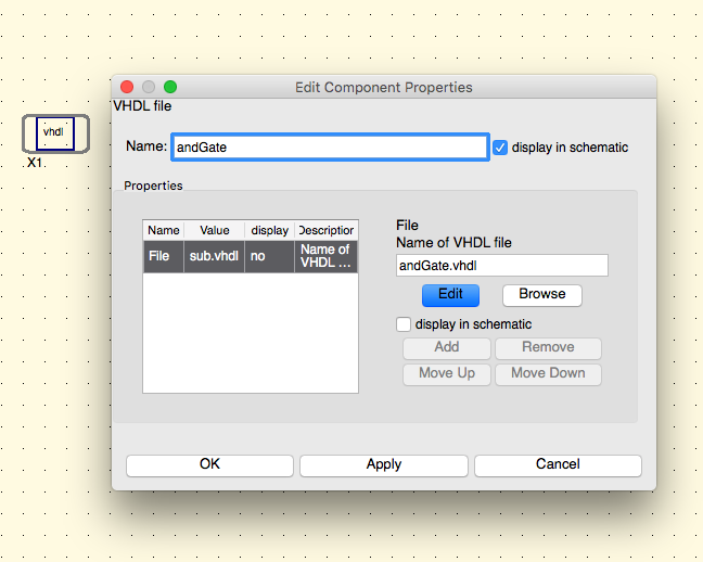
- Click on menu Insert > Insert Ports . Connect all ports for you schematic. Double click on each port and change it type for in or out depending on the port function. For this specific schematic port a and b are inputs and x is an output. Uncheck display in schematic check box for the variable Num for each port. Rename the ports for match to the VHDL entity ports (a, b and x).
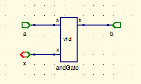
- Right click in the component and select Edit Circuit Symbol. using the text tool create the port name text (a, b and x) drag it close to each correspondent pin as below. Right click in the component and select again the Edit Circuit Symbol option to back to the schematic. Finally Save it and give the file the same name as the entity (i.e.: andGate.sch).
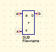
- Everything up to this point has been to create a sub-circuit, from our VHDL code, that can be simulated in a digital circuit. We can now assemble this digital circuit.
- Left click on New schematic tool or menu File > New.
- Select the Components tab in the left window. Select file component in the top drop-box and add a Subcircuit component to the schematic windows.
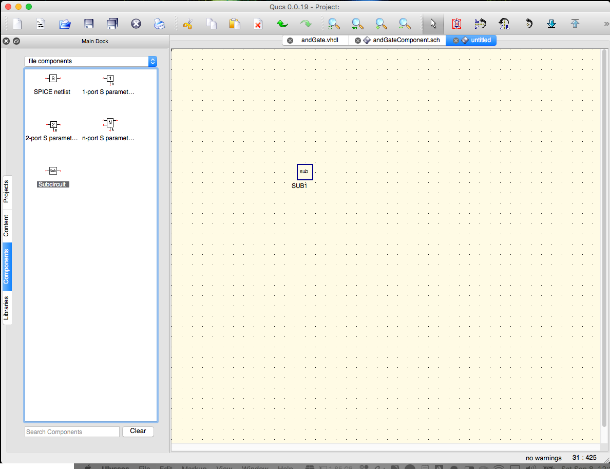
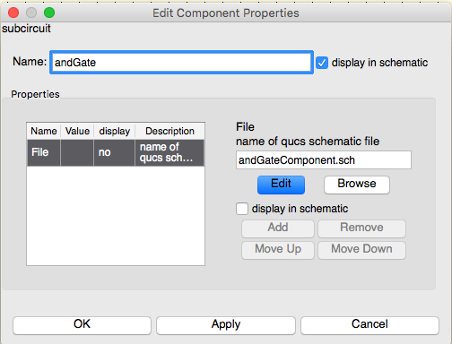
- Double click on the file component and browse to select your circuit saved on the step 9. Change the sub circuit name to andGate. Click OK.
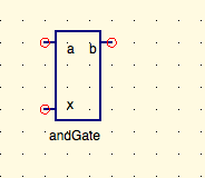
- Now the new component should be loaded as below.
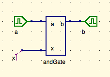
- In the Components tab of the left window, select digital components from the top drop-down box. Select digital source located at the top of the resulting list. Add two digital sources next to each sub circuit input. Rename each digital source to match the port name. Uncheck display in schematic check box for the variable Num for each digital source. Add a wire and name for the port x. You should have some thing like image below.
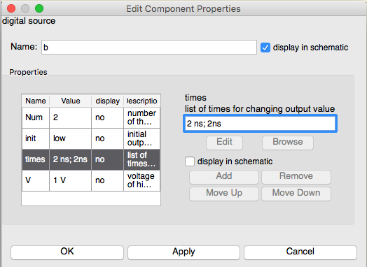
- Now double click on the digital source a and change its times parameter to 2ns; 2ns. Click OK.
- Under the Components tab in the left window, select simulations from the drop-down box. Add a digital simulation component into your circuit. Double click on the digital simulation component and change the property Type to TimeList instead TruthTable. Change the time parameter to 3
1 + 2( sum of all digital sources times).
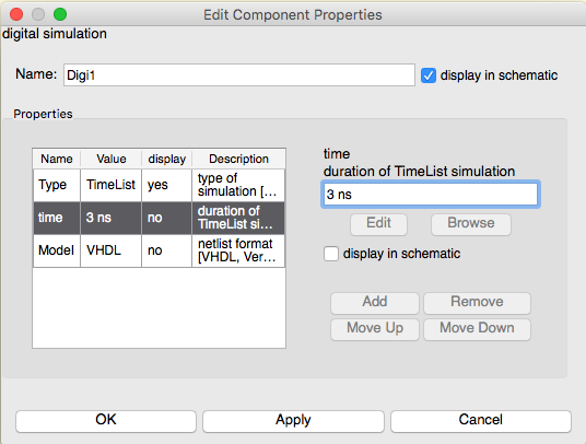
- Now it’s time to save the schematic. Use a proper name like andGateSimulation.sch.
- Press F2 function key to start the simulation. If errors occurred, you must correct them and re-simulate. If the simulation is successful, a new blank window will open. This window will be used to display our simulation results.
- With the Components tab selected in the left window, and diagrams selected from the top drop-down box, all of Qucs’ simulation output displays are visible. The proper display to select is governed by the type of circuit simulated. For digital circuits, both Truth Table and Timing Diagram are appropriate choices.
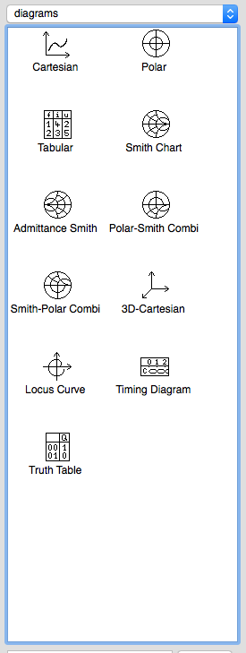
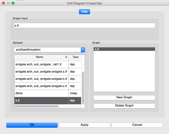
- First add a Truth Table diagram. Add the x.X value to the Truth Table the click OK.
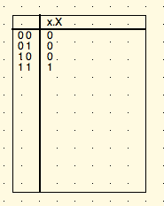
- You should see the follow Truth Table on the screen.
- Now it’s time to add a Timing Diagram. Select the input itens to display like the image below. Click OK.
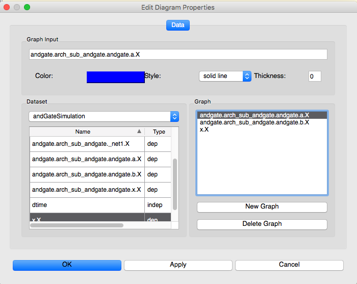
- On the schematic screen you should see a timing diagram as the picture below.
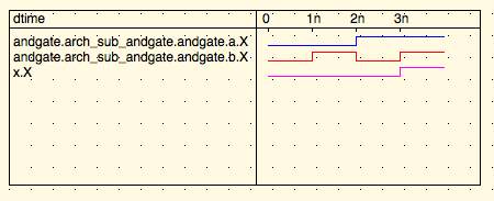
- Examination of the resulting truth table and diagram reveal that our VHDL code produces the correct output for all combinations of input.
3. Conclusion
This article showed how we can use a free and open source tool to simulate VHDL/FPGA code. All the simulation results match with VHDL code previously create. Thus we can see that Qucs is easy and very powerful to simulate VHDL / FPGA. But of course, more complex circuits can be simulated as need.
See you soon! Peace!!!🖖🏻