eBay Multimeter Repair. Was it a bargain!?
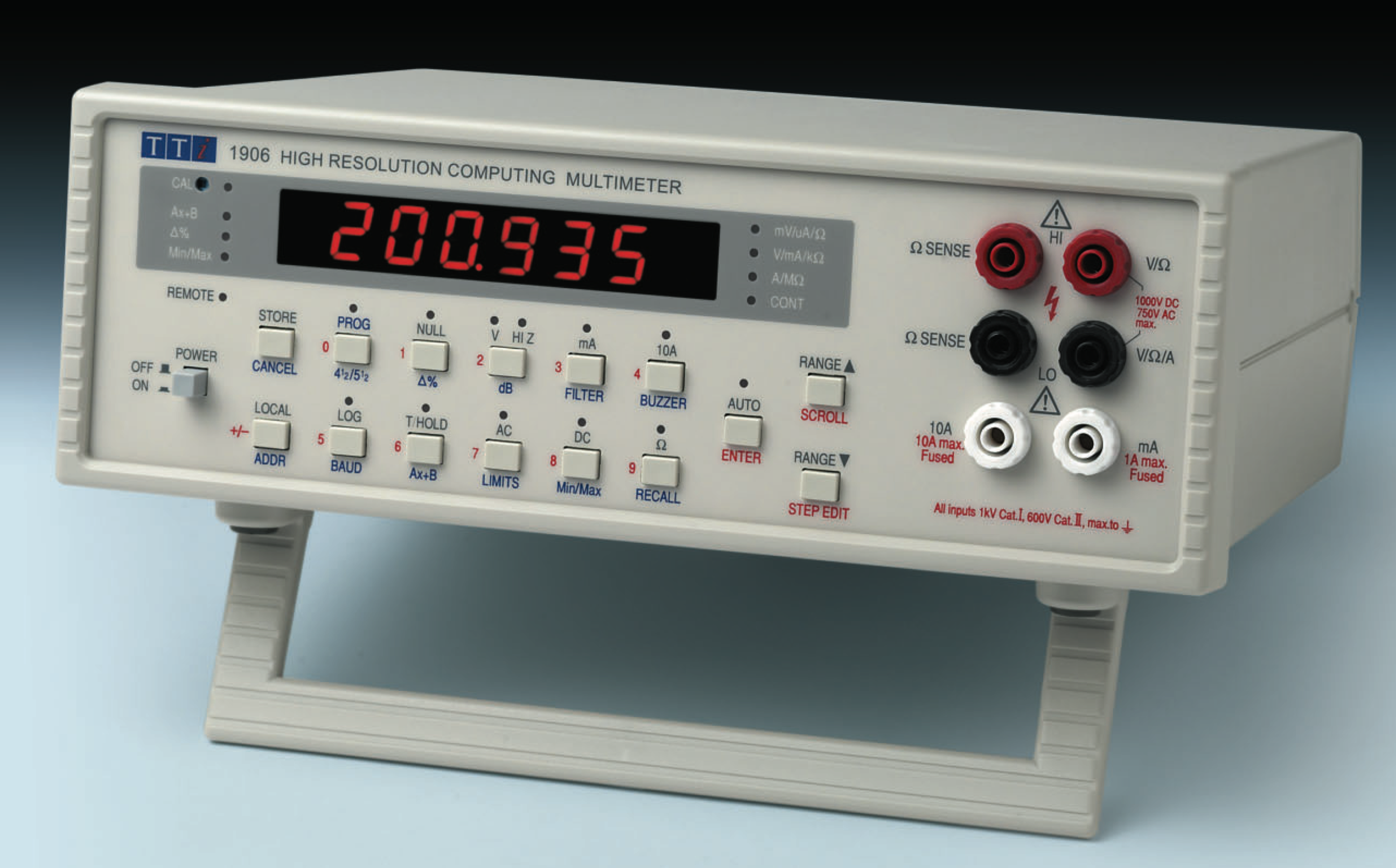
On my most recent eBay adventure I’ve bought a “for parts or repair” TTI 1906 5 1/2 bench Multimeter. Buying “for parts or repair” any equipment is always a leap of faith, as you never know the equipment real condition.
For my joy the Multimeter condition was not bad at all, needing some cleaning, testing and potentially some repair.
 TTI 1906 5 1/2 digits multimeter from eBay
TTI (THURLBY THANDAR INSTRUMENTS) is a British company which design and manufacture high quality electronic test equipment. The TTI 1906 is a 200000 Count1 Computing Multimeter2 with the following characteristics:
- High brightness 5 1//2 digit LED display
- 210,000 counts auto/manual ranging
- Auto-ranging or manual ranging
- 1uV, 1mΩ and 1nA sensitivity
- True rms a.c. ranges
- Current measurement up to 10 amps
- Null and Hold functions
- 100 reading data logger
- Wide range of computing functions: Ax+B, Hi-Lo-Pass, % deviation, min/max, dB
- Isolated RS-232 interface as standard
The TTI 1906 is a DISCONTINUED product, and more specifications can be found in the user manual available at TTI website here.
Initial Test
The Multimeter overall aesthetic condition was very good considering the age of the instrument3. The basic measurements tests were performed (AC/DC Voltage, AC/DC Current and Resistance).
The following test equipment were used to perform the initial Multimeter functionality check:
- AD584K4 Precision voltage reference (2.5V, 5.0V, 7.5V and 10V)
- Precision resistive decade box
- 20MHz Signal generator (used to test AC voltage)
Voltage and resistance tests were ok. The Multimeter 5.0 Vdc measurements was very closer to the calibrated reference source voltage of 5.00226. Same happened with the other voltage values and resistances.
 TTI 1906 measuring the 5.0V reference voltage
While testing the current measurement functionality, a fault was found on the 200uA current measurement scale, for both AC and DC. The Multimeter measured value was way lower than the actual current.
Repair
Once finished the functional tests, was identified that only fault found was with the 200uA AC/DC current scale.
Disassembling the TTI 1906
The TTI1906 plastic enclosure is formed by two halves held together by four metal screws on the bottom on the unit. Once these screws removed the enclosure can be easily opened.
 TTI 1906 PCB and power supply transformer
Input circuit
The Multimeter schematic can be found in the TTI1906 Service Manual. The schematic shows the 200uA input circuitry.
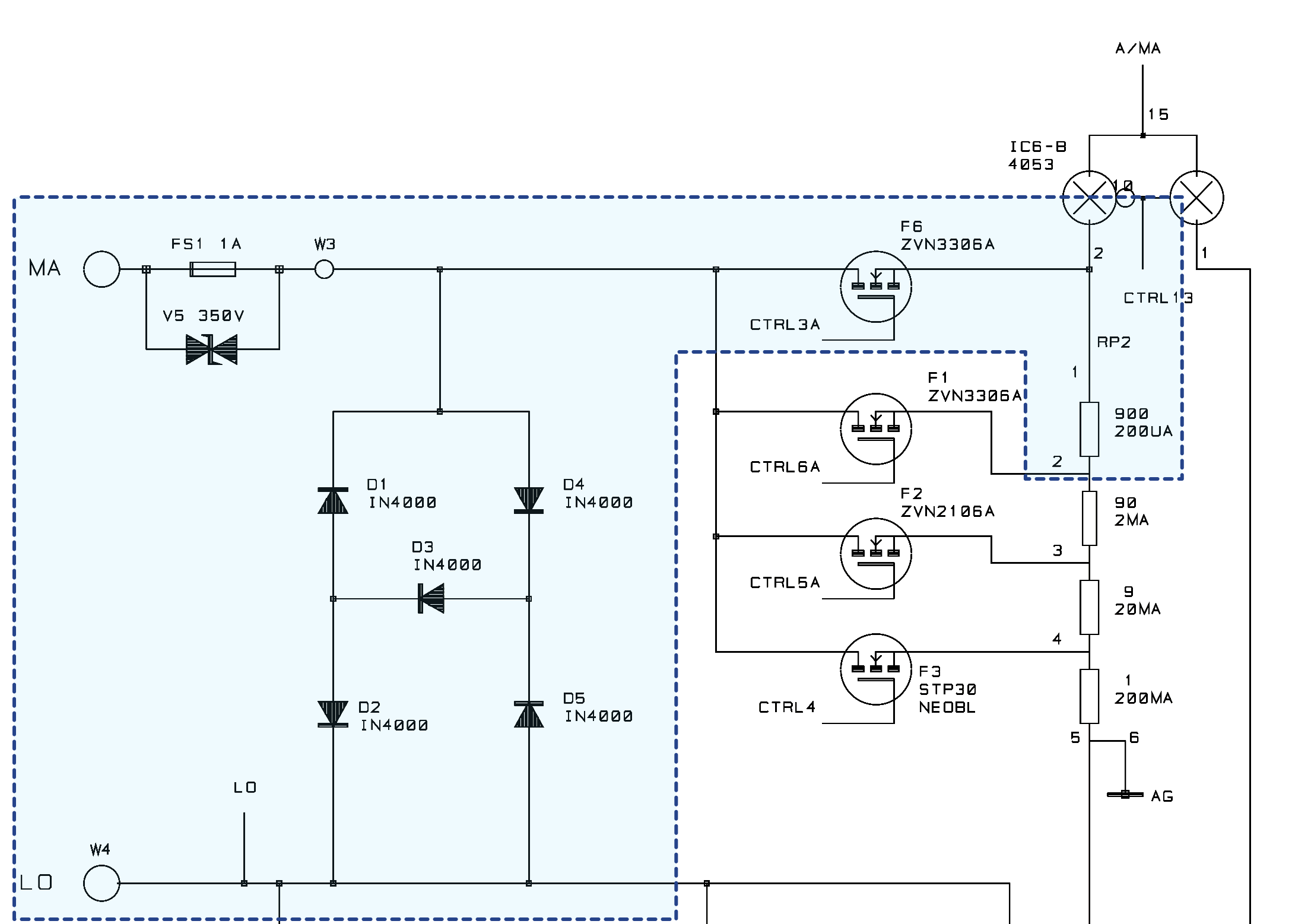 TTI 1906 200 uA input circuitry
The 200uA to 200mA current shunts are contained in RP2. The 200uA scale is switched into the appropriate shunt in RP2 by MOSFET transistor F6.
V5 prevent high voltage transients from occurring if the current is fed from an inductive source when the fuse blows; these could otherwise prevent the arc from extinguishing within the fuse body which could therefore result in instrument damage. VR5 uses a TVS symbol on schematic, however physically it’s a MOV (Metal-Oxide Varistor)5.
D1 to D5 protect the Multimeter current input for overload/overvoltage or connection mistakes, that may damage the switch MOSFET or the shunt resistor. In current measure mode a fuse can protect the multimeter input, however there are some limitations. One of this limitation is fuses do not blow sufficiently fast enough to protect the shunt resistor and MOSFET switch from destruction in case of a fast voltage transient. For this reason a 5-diode protection circuitry6 is added as a protection mechanism.
Troubleshooting
The transistor F6 was tested and no issues was found. Same for the shunt resistor RP2, Fuse FS1 and MOV V5.
Testing the protection diodes D1 to D5, I found D2, D3 and D4 damaged. Diodes D2 and D4 were dead short circuited, while Diode D3 shows a vary high leakage current.
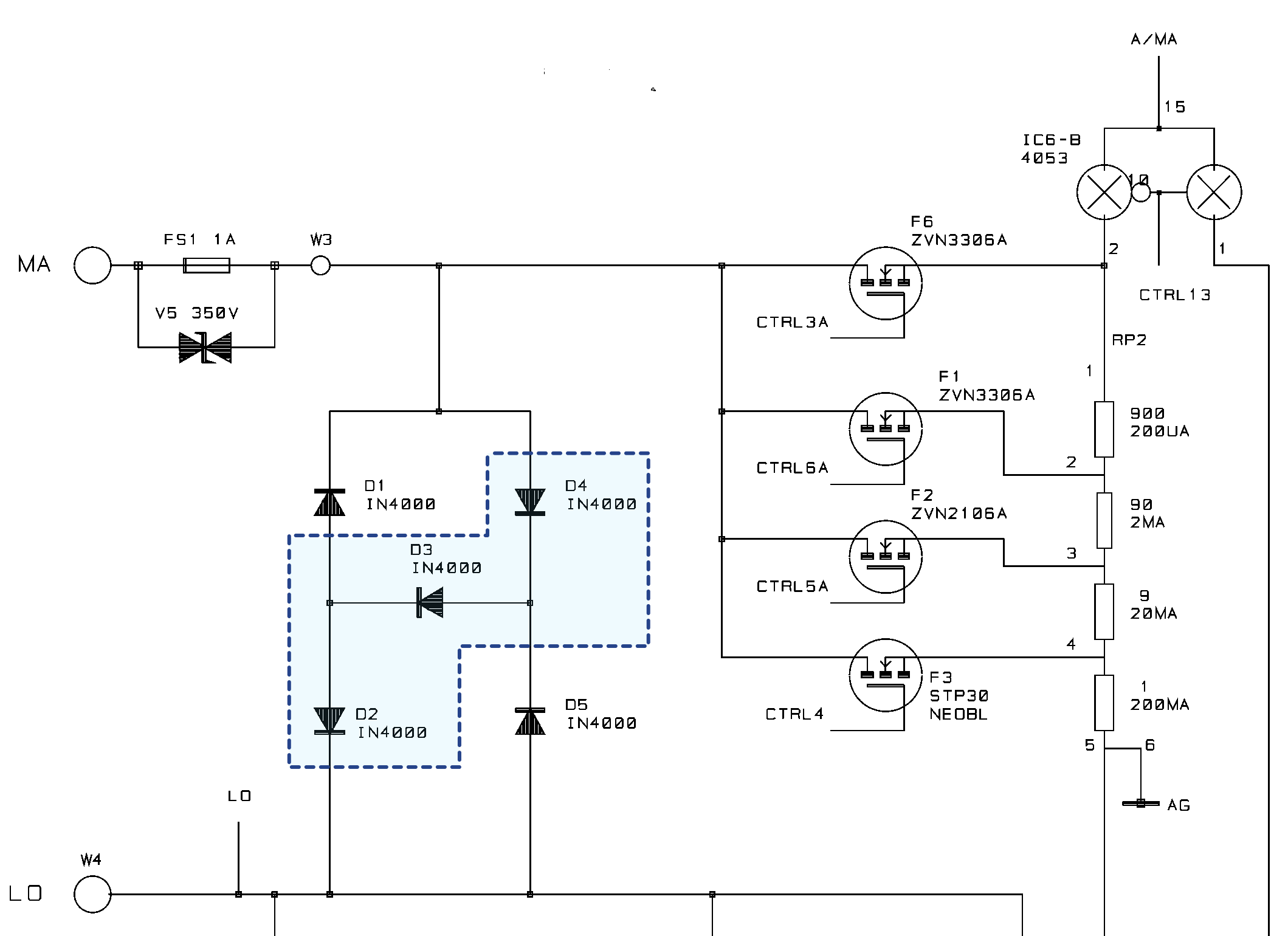 mA input circuitry faulty components
The main PCB showed some previous soldering work performed on the input diodes (D5), it maybe means the unit experienced similar fault before and was repaired.
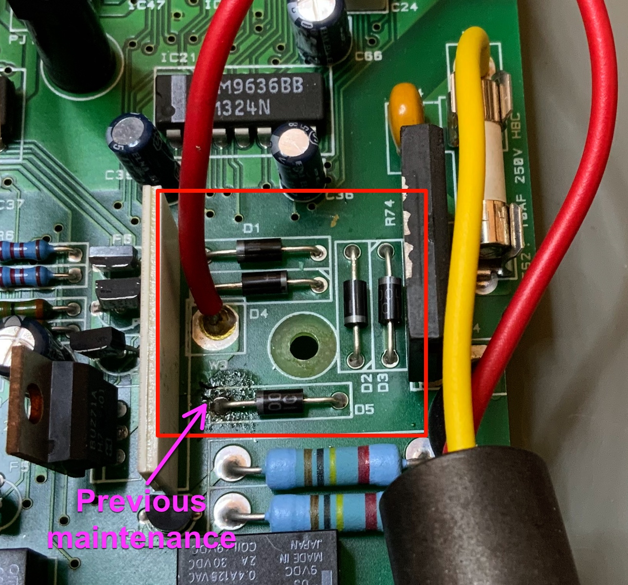 mA input circuitry faulty components location on PCB. Soldering signals on D5
I decided to replace all protection diodes D1 to D5 to avoid any further problems cause for potentially almost-faulty part.
After replaced the diodes, the unit was retested and the 200uA scale works ok.
Even as an uncalibrated7 instrument, I found all the TTI1906 multimeter measures very closer to the reference voltage source and to my Fluke 45 bench multimeter.
RS-232 communication test
Next step after finished the input circuitry repair was to test the RS-232 communication.
The multimeter serial interface uses the well known MC1488 and MC1489 line driver/receiver8 ICs. The serial lines are fully optically isolated via IC28 and IC30 photo transistors.
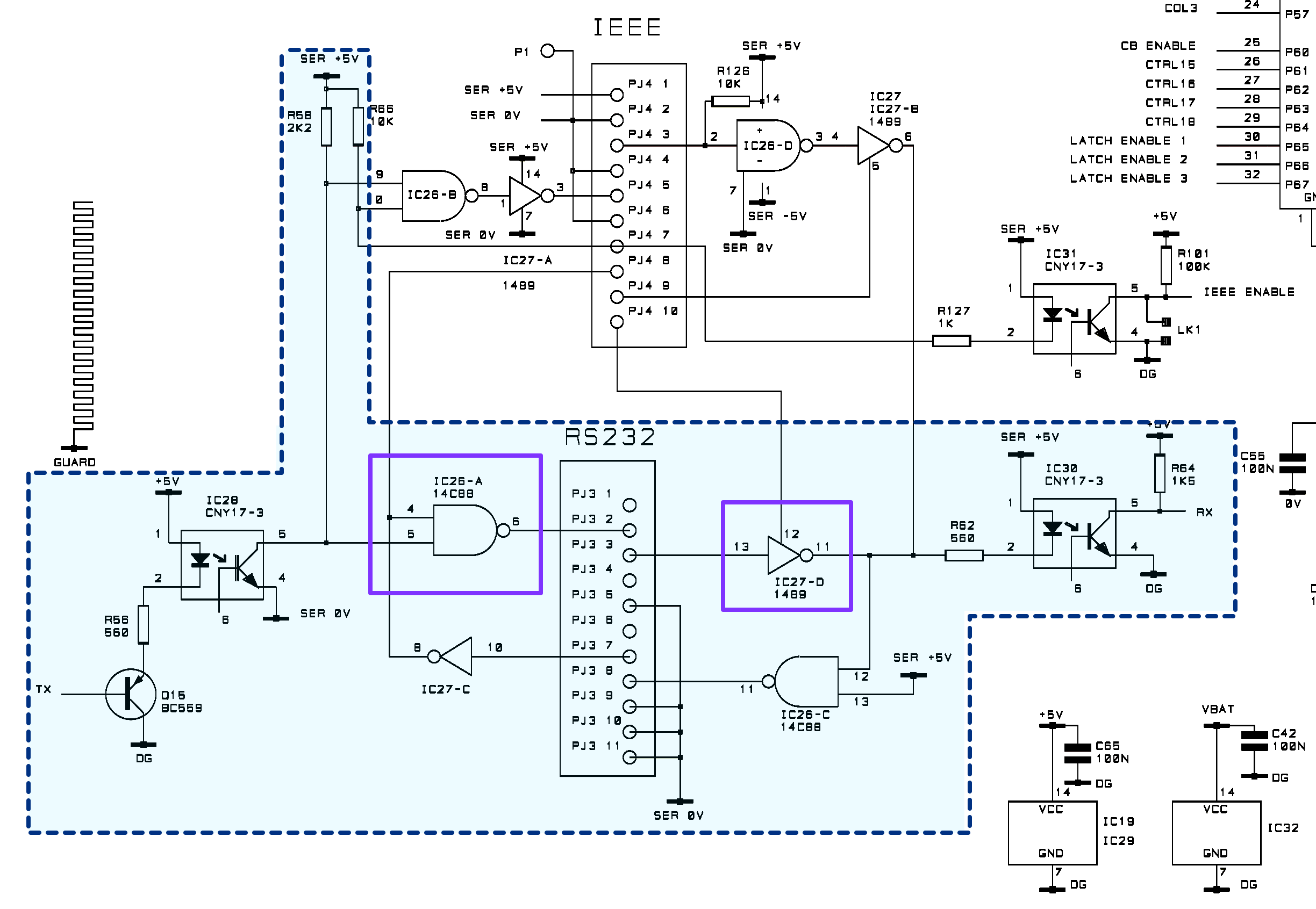 Serial input circuitry using 1488 and 1489 line drivers
A female 9-way D-type serial interface connector is located on the instrument rear panel. The pin connections are as shown below:
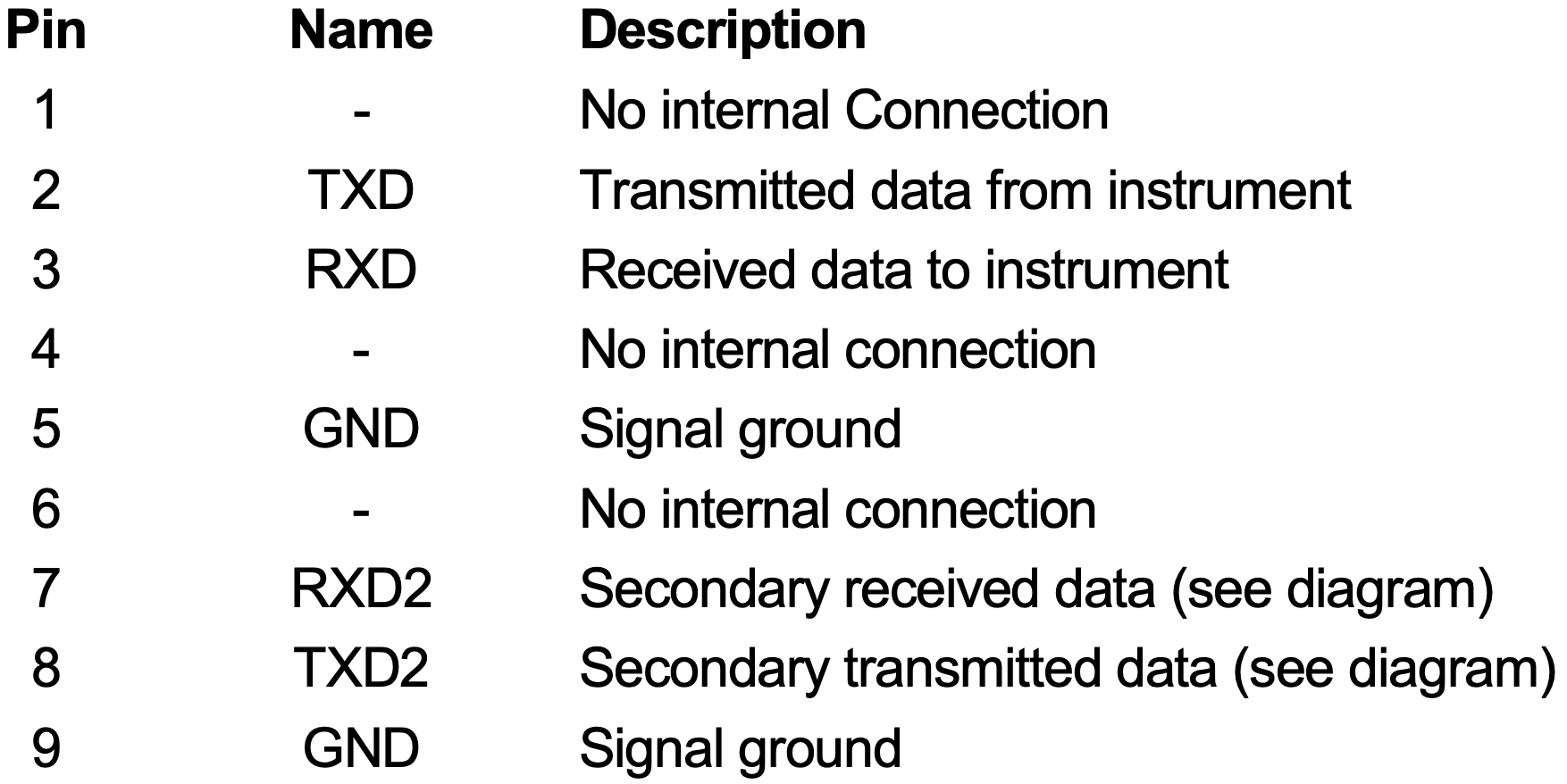 Serial connector signals
As described on the TTI1906 user’s manual, a RS232 serial cable with the following pinout needs to be used to connect the instrument to a computer serial port.
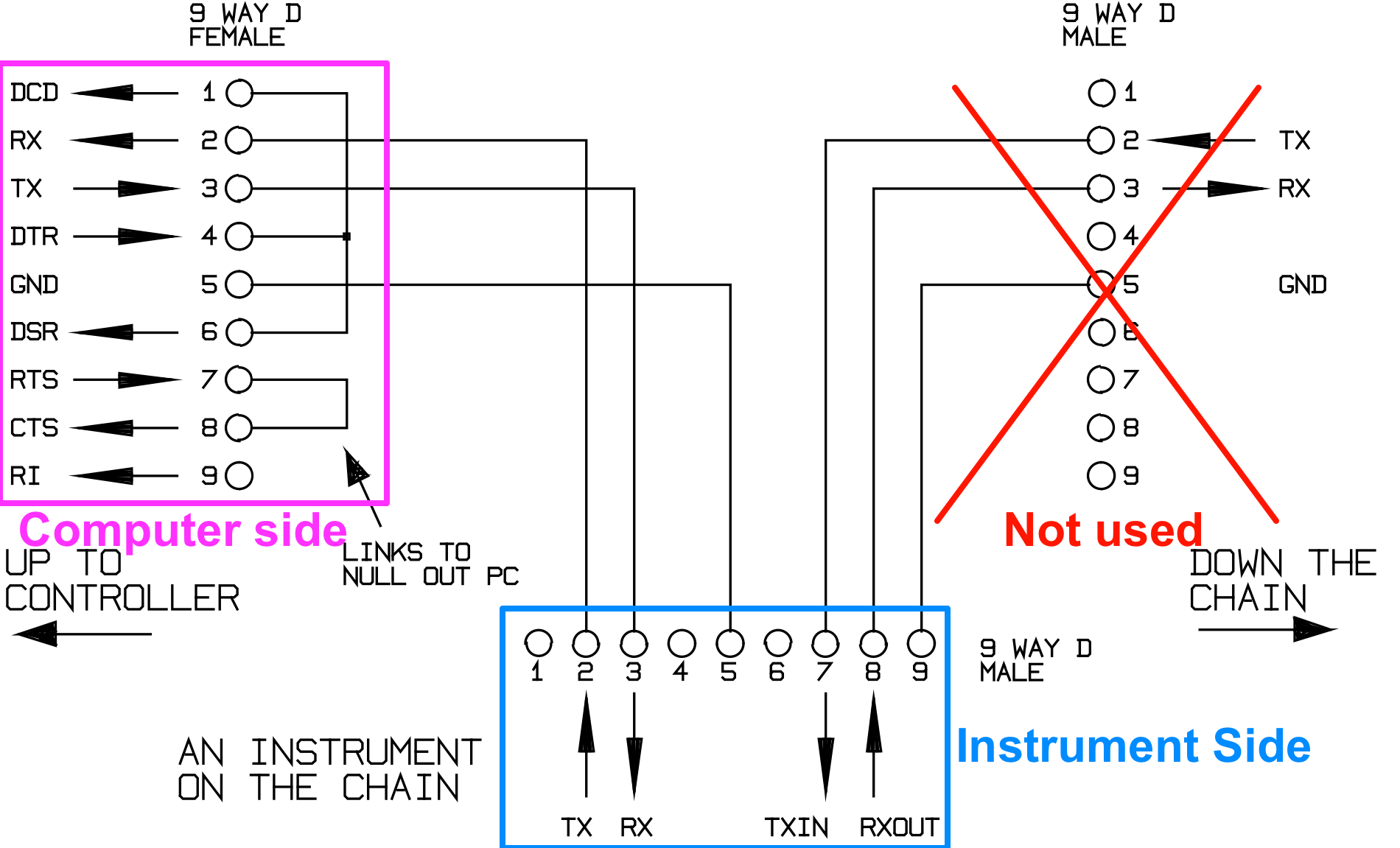 Serial cable pinout
the multimeter was then connected to a computer using the above serial cable via an USB to serial converter.
TTI developed a piece of software called ARC-WIN9 to send commands to the multimeter. Unfortunately is an old software that only run on Windows OS machines. The software can be downloaded HERE.
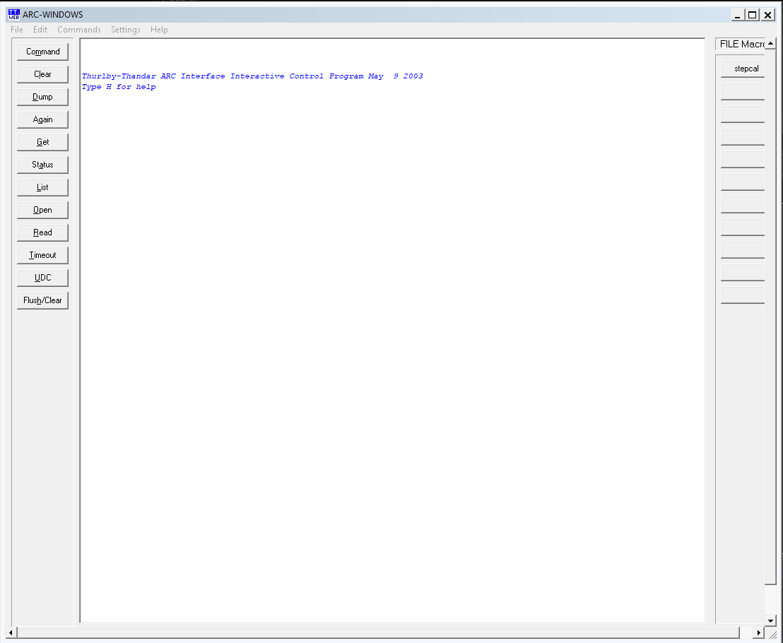 ARC Windows software
The RS232 communication worked like a bliss. I could send a *IDN? GPIB10 commands and receive information from the multimeter via serial port.
Some fun with python
I decided to play a little bit more around with the multimeter serial communication. I wrote a small piece of code in Python to get the instrument identification via GPIB. Full Python source is below.
After running the code the following output is displayed. It shows the instrument manufacturer (THURLBY-THANDAR), model identification (1906) and software version (1.18).
 GPIB Python code output
Going a little further on my Python adventures, I wrote a piece of code to read the data from the instrument and plot it. Full Python source code is below.
Running the code we can see the voltage reading on screen along with a line graph.
 Reading data via serial port graph
The software could be further improved to show more information and performer more instrument control commands.
Conclusion
I’d say that this eBay experience was great! It was really a bargain! I’ve bought a very good instrument for a fraction of the price of a similar instrument. However, bear in mind that things could not end so well, and I could end up expend my money in a useless bunch of scrap.
Before venture yourself to buy stuff to repair from eBay, performed some research first to find the equipment service manual, schematic, etc. Also, search on forums to understand how reparable the equipment could be.
Notes and references
-
Count means the maximum value that can be displayed. For example, if a multimeter has a specification of “4199 counts”. It means that 419.9V is the maximum value to display in the 420.0V range. The count is defined by removing the decimal point for each range. Generally, the larger the count value that can be displayed, the wider the range and the higher the resolution. ↩
-
Computing multimeters is the TTI designation for Multimeters that can execute computational operations/functions as: Ax+B, % deviation, Digital Filter, etc. Refer to the TTI 1906 user’s manual to see the complete list of computing functions. ↩
-
My multimeter is the first TTI1906 version with blue enclosure. The new version that’s also obsolete, has a white enclosure.
 TTI1906 with white enclosure ↩
 -
The AD584K is an 8-terminal precision voltage reference offering pin programmable selection of four popular output voltages: 10.000 V, 7.500 V, 5.000 V and 2.500 V. It can be found in very popular kits all over the internet with voltage selection option.
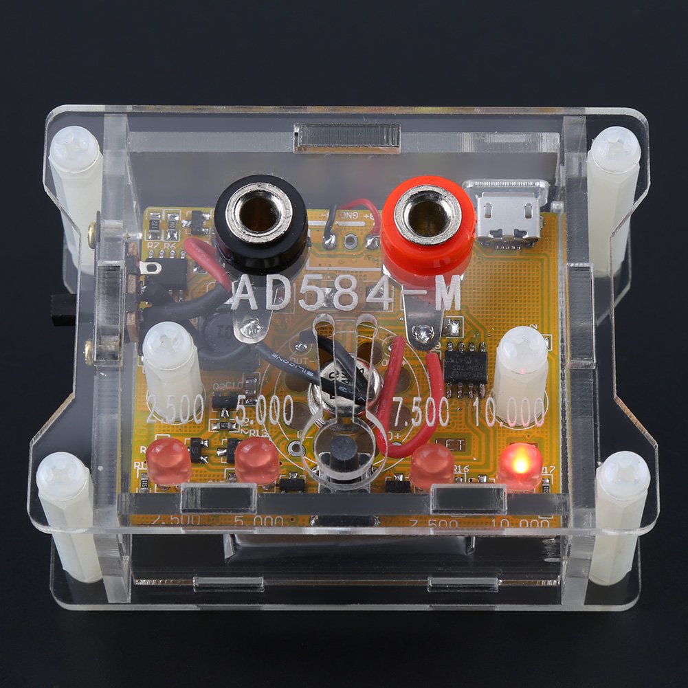 AD584K voltage reference kit ↩
 -
On this application the MOV is used as transient suppressor. When the current in inductive load is interrupted by mechanical contacts or when the fuse blows, the voltage across the contacts builds up and causes arcing which is destructive to the instrument. MOVs can be then applied to prevent initiation of the arc.
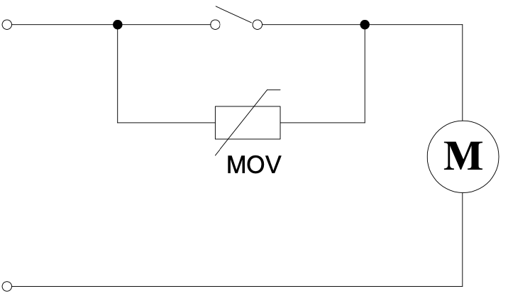 MOV used as contact protection ↩
 -
This kind of protection solution can be built either with a bridge and one extra diode - as does Fluke on some Multimeter - or with 5 diodes as the case of TTI1906 multimeter. For this given protection circuit, 3 diodes are present all the time with either polarity (±), that way protecting the input.
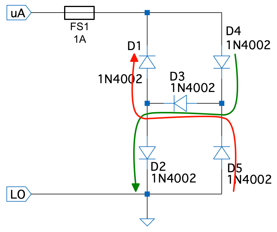 5-Diodes bridge flowing currents
Under an overvoltage the current increase rapidly blowing the fuse and protecting the instrument as shown on the image below.
 5-Diodes overvoltage graph ↩
 -
The instrument can be calibrated via serial communication as described on the service manual. Some very basic information about the multimeter calibration process can be found HERE. For precision work I recommend send the instrument to a calibration house to be properly precision calibrated. ↩
-
The MC1488 / MC1489 are monolithic quad line driver and receiver designed to interface data terminal equipment with data communications equipment in conformance with the specifications of EIA Standard No. EIA−232D (RS-232). They basically work as translator between the RS-232 levels (±12V) to DTL (Diode-Transistor-Logic) levels (0 to VCC - in this case 5 Vdc - ). Both ICs are also compatible with TTL logic.
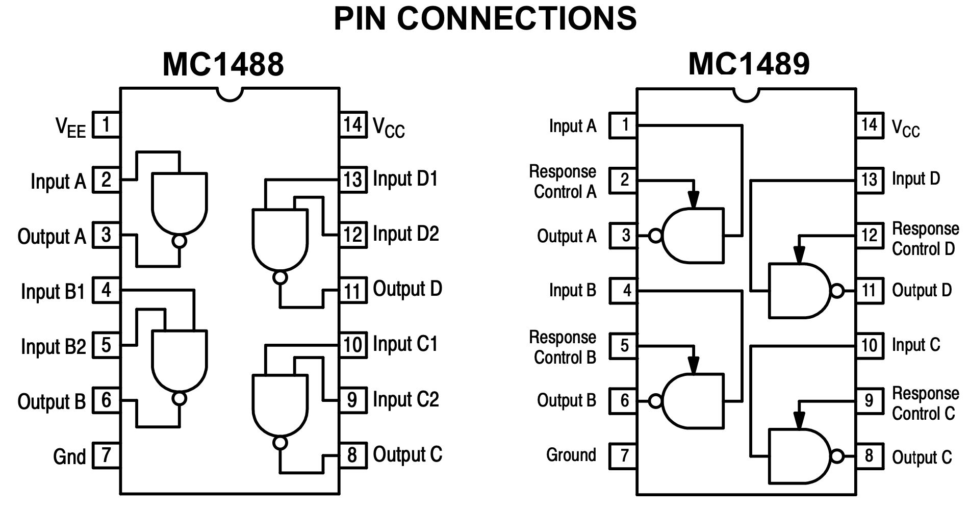 MC1488/MC1489 RS-232 driver/receiver pinout. https://www.onsemi.com/
Below are further sources of information about the RS-232 standards:
-
The eevblog forum has a very good message thread (HERE) about this software and additional TTI1906 multimeter information. ↩
-
The GPIB interface, sometimes called the General Purpose Interface Bus (GPIB), is a general purpose digital interface system that can be used to transfer data between two or more devices. It is particularly well suited for interconnecting computers and test instruments.
 Example of GPIB command format ↩